System Geometry
The geometry of the sputtering system is useful to know when designing processes such as lift-off. The deposition of material in a sputtering system is directional with some spread. The AJA ATC 2200 UHV sputtering system is equipped with 6 guns and a rotating chuck. The guns are arranged in a ring around the chuck. The angles of the guns are adjustable. The chuck position is adjustable. Figure 1 is a diagram of the sputtering system.
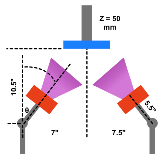
The gun angle is adjustable using a linear drive. The actuator settings are in units of [mm], which corresponds to the linear displacement of a rod. The table below correlates the linear drive settings to the actual gun angle, θ in Figure 1. An approximation of the gun angle is:
θ = -1.5*X + 39,
where X is the linear drive setting.
The chuck position is controlled by a linear drive. The settings on the chuck position corresponds to the position of the rod. It does not correspond to the sample to gun distance, but it does have a certain relationship. In the diagram in Figure 1, the chuck position is set at Z = 50 [mm]. When Z is changed to 30 [mm], the chuck is displaced by 20 [mm] downwards along the shaft. Although the chuck is closer to the guns, it is not 20 [mm] closer. To further complicate this the wafer to gun distance also depends on the chuck used. A wafer on the 3″ magnetic chuck is 10 [mm] lower than a wafer on the 3″ Inconel chuck. Nonetheless, if the working distance is important, it can be estimated from the information provided by the diagram in Figure 1. The working distance can be calculated using a custom function on this google spreadsheet. When using the standard processing conditions at UHNF, the sample to target distance is approximately 17cm.