An electron beam writer exposes a shape by discretely scanning a focused electron beam across the pattern. This produces a shot pattern that fills the shape. Typically the spacing between each shot is smaller than the beam size resulting in a solid exposure of the shape. Shapes are exposed one by one until the entire pattern is complete.
Shot Filling
Shot filling is a term used to describe the process by which an electron beam writer draws a primitive. Most electron beam writer use a shot filling strategy called the Simple Manhattan, but Jeol uses a unique proprietary algorithm. Shot filling can have a significant impact on the fidelity of an exposure. By understanding the basics of shot filling, one can prepare a layout with more control of how a shape is exposed.
The image below is an example of how the simple manhattan algorithm shot fills a couple of primitives. The two primitives are right triangles with the exact same dimensions but different orientation. Each circle represents a single shot from the electron beam writer. The position of the shots are snapped to a discrete grid with a resolution of 20 nm (shot step or shot pitch). When the primitive is exposed, the electron beam is scanned from one spot to the next along a horizontal line. At each spot, the electron beam idles for a fixed amount of time depending on the desired dosage. At the end of the line, the beam will blank before exposing the next line. The beam also blanks from one primitive to the next.
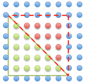
The total dosage for each primitive is equal to the number of shots enclosed in the primitive. From figure 1, the green triangle has 15 shots and the red triangle has 10 shots. This is a 33% or 50% disparity in the actual dosage of the primitive depending on which triangle you want to use as the reference dose. The dose disparity is caused by the discrete nature of the beam scanner and is influenced by factors such as primitive dimensions, primitive orientation and shot filling algorithm. In general, the effects of shot filling is not visible until the dimensions of the primitives are close to the shot step.
Shot Step (Shot Pitch)
The shot fill depends on the shot step and the dimensions of the primitive. The minimum shot step is determined by the specification of the system, the beam current and the sensitivity of the resist. The minimum shot step can be estimated by:
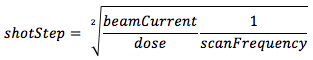
where,
- shotStep : minimum scan step between shots
- beamCurrent : beam current during exposure
- dose : area dose
- scanFrequency : scan frequency of the tool
For example, the JBX-5500FS has a scan frequency of 12 MHz. So, for a dose of 200 [uC/cm2] and a beam current of 1 [nA], the shot step is approximately 6.45 [nm]. The scan resolution of the JBX-5500FS in Mode 2 is 5 nm, so the minimum shot step we can specify for the exposure is 10 nm — shot steps must be a 1 or an even multiple of the scan resolution. If instead, a current of 10 [nA] is desired for the exposure to reduce the write time by a factor of 10, the shot step must be increased to 30 nm. As the shot step becomes larger, it can have a significant effect on the dosage of a primitive depending on its dimensions.
Shot Step vs Dosage
To demonstrate how the discrete nature of the scan system affects the actual dosage of a primitive, consider the two cases in figure 2.
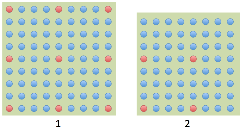
Case 1 is a square 45 nm wide and case 2 is a square that is 40 nm wide. The blue dots represent the shot fill when the shot step is 5 nm. The red dots represent the shot fill when the shot step is 20 nm. Since the shot step of the red dots is 4 times larger than the blue dots, each red dot exposes the square at a dosage that is 16x more than a blue dot. By counting the dots and multiplying by their dose factor, we can determine the actual dose for the exposure of the squares. The table below compares the actual dosage of each square at different shot step.
| Shot Step | Dose Case 1 | Dose Case 2 |
|---|---|---|
| 5 nm | 81 | 64 |
| 20 nm | 144 | 64 |
From the table, it is evident that the 40 nm wide square is exposed at the same dosage at 5 nm or 20 nm shot step. On the other hand, there is a significant discrepancy between the dosage at each shot step for the 45 nm wide square. This discrepancy is due entirely to the discrete nature of the scan system in electron beam writers. A simple rule to help avoid dosage discrepancy is to design the size of the primitive to be an integer multiple of the shot step.
For rectangular primitives using the simple manhattan shot filling algorithm, the actual dosage can be estimated using the following equations:
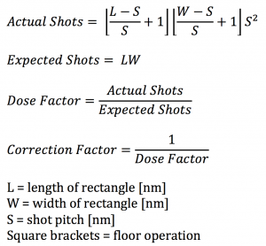
From the equation above, it is clear that selecting a shot pitch that is a scalar factor of the dimension of the rectangle will reduce the dose error to zero. In general, selecting a shot step that is much smaller than the dimensions of the primitive minimizes the dose error. In practice, there is a trade off between small shot steps and beam current. In other words, there is a compromise between scan fidelity and print speed.
Simple Manhattan Shot Filling Algorithm
The simple manhattan is a straightforward shot filling algorithm, as shown in Figure 1. I believe most electron beam writing systems use the simple manhattan. The rules of the simple manhattan algorithm is:
- Begin at the origin of the primitive — usually the bottom left corner of a box that tightly evelopes the primitive.
- Generate the shot positions by:
- (x,y) = (S/2 + N*S, S/2 + M*S)
- S : shot pitch
- N, M : integers
- (x,y) must be inside or on the edge of the primitive
- (x,y) = (S/2 + N*S, S/2 + M*S)
Jeol Shot Filling Algorithm
The Jeol shot filling algorithm is propriety. It is different from the simple manhattan algorithm.
Writing Order
The order in which the beam exposes each shape depends on the order the shape data is stored in the pattern file. This means that shapes that are physically next to each other may not be printed in sequence. The writing order should be controlled to avoid placement errors for sensitive device patterns.
Patterns printed in the proper order will have less drift between adjacent primitives. The beam position drifts unpredictable with respect to the stage. There are many factors that affect the drift rate such as room temperature and humidity, stage temperature, working distance, and electron beam column condition. In the case of extreme beam drift, one may observe gaps or overlaps between adjacent patterns. The drift rate for the JBX-5500FS is typically less than 100 [nm/hr].
The converters provided by the manufacturer does not attempt to order the pattern. Ordering is a time consuming process and a difficult problem. The algorithm for write order would be similar to the traveling salesman problem used to plan delivery routes for shipping companies. Write ordering is offered by third party developers.