Sample Heating
The ion mill system delivers heat to the sample via radiation and ion beam bombardment. A student has observed that a 3″ wafer positioned 15 cm from the ion source can reach 100 °C just from radiation from the neutralizer filament. Milling the wafer for a minute heats it up to over 260 °C! These measurements were made using heat sensitive stickers placed on the back side of the wafer, so thermal contact to the sample holder is poor.
For pattern transferring processes with a resist mask, these temperatures are high enough to cause the resist to reflow. For heat sensitive materials, this can cause a degradation in its performance. Some resists become nearly impossible to strip if exposed to enough heat. Sample heating is a real issue for ion beam milling systems. A basic understanding of heat transport can help keep samples cool during the milling process.
Specific heat is a material property that specifies the amount of energy required to raise the temperature of a material by 1 °C. The table below lists the specific heat of some common materials. For example, let us use a 3″ silicon wafer with a surface area of approximately 44 cm2 and a mass of 5.12 [g]. When it is placed 15 [cm] from the ion source, it will receive approximately 0.39 [W/cm2] of energy from ion beam bombardment. This will cause the wafer to heat up at a rate of 4.8 [°C/s]. When the wafer is placed 30 [cm] from the ion source, it will receive approximately 66% less energy, reducing the heating rate of the wafer to 1.68 [°C/s]. For these calculations, it is assumed that the wafer does not lose the heat to its surroundings. This assumption is not true, but it provides a sense of how hot the wafer can get when being milled.
To further illustrate the problem, the amount of material milled is proportional to the energy delivered to the wafer, which is proportional to the amount of time that the wafer is exposed to the ion beam. The milling rate for silicon is approximately 9 [nm/min] under the conditions where the wafer heats up by 4.8 [°C/s]. Therefore, to mill just 50 [nm] of silicon will heat up the wafer by up to 1600 degrees! In reality, the wafer will not get that hot because the wafer will lose heat by radiation and conduction.
| Material | Specific Heat [J/gK] |
| Aluminum | 0.902 |
| Steel | 0.490 |
| Silicon | 0.703 |
| Silicon Dioxide | 0.730 |
| Glass | 0.840 |
| Water | 4.186 |
Heat Conduction
Heat can be transferred from an object to its surroundings via conduction when they are in contact. The heat transfer equation is:
Q = (dT)Ak/x,
where Q is the heat transferred in [W], dT is the difference in temperature along the thickness of the material in units of [°K], A is the area in units of [m2], k is the thermal conductivity of the material in units of [W/mK] and x is the thickness of the material in units of [m]. For layers of different materials, the temperature difference between the hot and cold side is:
dT = Q/A(x1/k1 + x2/d2 + x3/k3 + … xn/kn),
where the variables are the same as previously defined. The thermal conductivity of various materials is listed in the table below. The heat transfer equation is quite intuitive. Materials property aside, heat transfer is most efficient if the heat does not have to travel very far and is able to pass through a large area; and of course, heat transfer is faster when there is a larger temperature difference.
| Material | Thermal Conductivity [W/mK] |
| Aluminum | 205 |
| Silicon | 150 |
| Silicon Dioxide | 1.4 |
| Helium | 0.142 |
| Copper | 401 |
| Thermal Paste | 5 |
| Thermal Sheet | 5 |
| Vacuum | 0 |
It is important to realize that the thermal conductivity of a vacuum is 0. When a rigid sample such as a silicon wafer is fixed onto a rigid sample holder, there is not much contact between them since both objects are not atomically flat. In this situation, it is safe to assume that heat generated on the wafer does not effectively conduct towards the sample holder. There are several methods used to improve thermal conductivity between the sample and the holder and they all involve filling the space/void with something more thermally conductive than vacuum.
- Fill the space with PTFE Oil
- Fill the space with thermal paste
- Fill the space with helium
- Fill the space with thermal sheet
Heat Radiation
Heat can be transferred from an object to its surrounding by radiation. This process does not require the object to be in physical contact with anything. For example, the sun is a source of radiant heat, sharing its energy to the entire solar system by emitting electromagnetic waves. We experience the sun’s radiated energy as warmth and light. The thermal energy radiated by a blackbody radiator is given by:
P = eσA(T4-Tc4),
where P is the radiation loss in [W], e is the emissivity of the object, A is the surface area of the object in [m2], σ is Stefan’s constant (5.6703×10⁻⁸ [W/(m2K4)]), T is the temperature of the object in [K] and Tc is the temperature of the surroundings in [K].
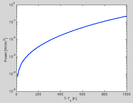
Figure 1 is a plot showing the radiated power per unit area assuming an emissivity of 1. When the wafer is 1000 degrees hotter than the surroundings, it’ll radiate power at a rate of 0.23 [W/cm2]. This is approximately half the amount of power delivered to the wafer from the ion beam. This calculation assumes that the surroundings do not heat up and the emissivity is 1. For the sake of the argument, we can assume an emissivity of 1 in order to determine the maximum power loss from radiation. Even under the most favorable assumptions/conditions, the sample will continue to heat up beyond 1000 degrees because it can not cool down by radiation as quickly as it is being heated up by the ion beam. In fact, the wafer will continue to heat up until about 1200 [°K] hotter than its surroundings before it can radiate as much power as it receives. Therefore, radiative cooling is not a viable option to manage sample heating during ion milling.